 July 31, 2026
T.LaneTonya
How to Install an Aftermarket TPMS: A Step-by-Step Guide for RV and Truck Owners
 Grundig Auto · TPMS Installation Guide
How to Install an Aftermarket TPMS: A Step-by-Step Guide for RV and Truck Owners
From choosing the right system to the first verified highway reading — the complete installation process for external valve-stem TPMS sensors.
Installing an aftermarket tire pressure monitoring system on an RV or commercial truck takes less than 30 minutes and requires no tools beyond a valve stem cap wrench and a calibrated pressure gauge. The sensors thread directly onto the existing valve stems — no tire dismounting, no specialist equipment, no modification to the vehicle. What does require attention is the sequence: sensor installation, pairing, cold-pressure verification, and threshold configuration all need to be completed in the right order before the system is genuinely ready to provide accurate monitoring. Skipping or reversing steps in this sequence produces a system that appears functional but may be providing inaccurate readings or incorrectly configured alarms.
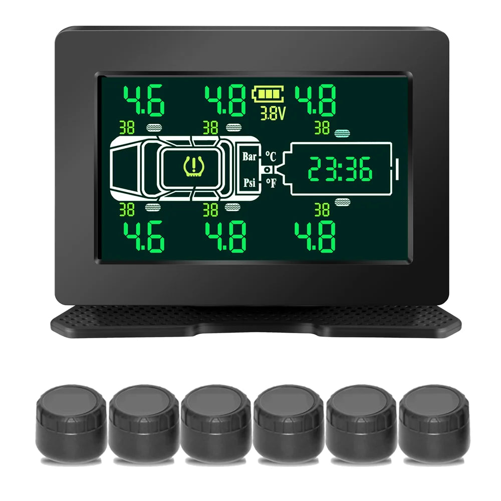
This guide covers the complete installation process for external cap-style TPMS sensors — the type used on the Grundig RV TPMS, Solar 6-Wheel, and S08 systems. It covers sensor installation, monitor positioning, pairing, baseline pressure verification, and threshold configuration, in the order these steps should be completed for reliable first-use operation.
Before You Start
What to Prepare Before Installing the First Sensor
Total Time20–30 minutes Tools NeededValve cap wrench, calibrated gauge Tire ConditionCold tires only — do not install after driving Skill LevelNo mechanical experience required Critical prerequisite — install on cold tires only: TPMS sensors must be installed and the baseline pressure verification completed while tires are cold — at ambient temperature, before any driving. Installing sensors and immediately verifying readings after driving gives a warm-tire pressure reading that does not match the cold inflation specification, leading to incorrect threshold configuration. Allow at least 3 hours of rest after driving before installing sensors.Step-by-Step Installation
The Complete Process From Box to First Reading
1Identify and Label Each Sensor
External TPMS sensors are pre-labelled or assigned position codes (FL, FR, RL, RR, etc.) before shipping. Before installation, identify which sensor corresponds to which position. Some systems allow position labelling through the monitor — if so, note the sensor serial number or code for each position before removing them from the packaging. Installing sensors at random positions and relying on the system to identify them after the fact takes longer and risks incorrect position assignment.
2Set Correct Cold Inflation Before Installing Sensors
Before installing any sensor, set every tire to the correct cold inflation for your vehicle's actual loaded weight. Use a calibrated gauge — not an estimate. This step happens before sensor installation, not after, because the pressure baseline that sensor readings will be verified against needs to be accurate before the sensors go on. Write down each position's gauge reading.
3Remove the Existing Valve Caps
Remove the standard valve caps from all positions where sensors will be installed. Inspect each valve stem for damage — cracked or corroded valve stems should be replaced by a tyre shop before sensor installation, as a leaking valve stem defeats the purpose of pressure monitoring and will produce constant low-pressure alarms.
4Install Sensors — Finger-Tight Plus Quarter Turn
Thread each sensor onto the valve stem by hand until snug. Use the valve cap wrench to add approximately a quarter turn — firm but not overtightened. Overtightening can damage the valve core and cause a slow leak from the seal between sensor and stem. The sensor should be secure with no detectable play, but should not require significant force to seat.
5Mount the Monitor in the Cab
Position the monitor display where it is visible from the driver's seat without requiring the driver to look away from the road for more than a glance. Windshield mount or dash mount positions are both acceptable — the priority is that the driver can read all position readings and respond to alarms without leaning or searching. Route the power cable to a switched 12V outlet or USB port so the monitor powers on with the vehicle.
6Pair All Sensors to the Monitor
With all sensors installed and the monitor powered on, enter the pairing mode on the monitor (refer to the specific system instructions — typically a long press of the pair or set button). The monitor will prompt for each position in sequence. At each prompt, activate the sensor at that position by pressing briefly with a pen or sensor activation tool — the sensor transmits an identification signal that the monitor registers. Confirm each position is accepted before moving to the next. Complete pairing for all positions before exiting pairing mode.
7Verify Readings Against Gauge Check
Once all sensors are paired and displaying readings, compare every position's TPMS reading against the gauge check you recorded in Step 2. Each reading should match within 1.5–2 PSI. A discrepancy greater than 3 PSI on any position indicates either a sensor installation issue, a valve stem leak from the installation, or a sensor that is not reading correctly. Investigate any position showing a discrepancy before driving.
8Configure Alarm Thresholds
With verified cold-inflation readings as the baseline, configure alarm thresholds: low pressure alarm at 15–20% below correct cold inflation, high pressure alarm at 15% above, and high temperature alarm at 175–185°F. Do not leave factory defaults in place — factory defaults are calibrated for passenger car pressures and will generate constant false alarms on commercial van and RV tires at 60–120+ PSI.
9First-Drive Verification at Low Speed
Before returning to highway speed, drive at 20–30 mph for 5–10 minutes and confirm that all positions continue transmitting and that readings are stable. A sensor that loses signal at low speed has either a pairing issue or an installation problem. Confirm all positions are transmitting before proceeding to highway speed. On the first highway drive, monitor readings actively for the first 30 minutes to confirm normal warmup patterns across all positions.
Choose Your System
Select the Right TPMS Before You Install
RV · Class B/C · TowingGrundig RV TPMS
116 PSI, 4/6/8-wheel. External cap sensors install in under 30 min. 5.0" display, configurable thresholds. Covers most RV and towing configurations. $119.
$119
Shop Now → Dually TrucksSolar TPMS 6-Wheel
6 external cap sensors for all dually positions including inner duals. Solar + USB monitor — no monitor battery needed. Same 9-step installation process.
$109
Shop Now → Heavy CommercialGrundig S08 TPMS
218 PSI ceiling, 8/12-wheel. Same external cap installation — no tyre dismounting. Purpose-built for Class A diesel and heavy commercial. $259.
$259
Shop Now → The installation principle that determines first-use accuracy: The system is only as accurate as the baseline you give it. Set cold inflation correctly before installing sensors, verify readings immediately after pairing, and configure thresholds based on the actual verified cold-inflation values — not the sidewall maximum, not a remembered number, and not factory defaults. These three steps take an extra ten minutes and are the difference between a monitoring system that works correctly from the first drive and one that generates alarms the driver learns to ignore.Install in 30 minutes. Monitor every mile after that. RV TPMS $119 · Solar 6-Wheel · S08 $259 · Free shipping
Shop All TPMS → Share